- 您现在的位置:买卖IC网 > Sheet目录3879 > PIC24F08KL401-I/SS (Microchip Technology)IC MCU 16BIT 8KB FLASH 20-SSOP
CHAPTER 7 16-BIT TIMER/EVENT COUNTERS 0 AND 1
User’s Manual U15905EJ2V1UD
237
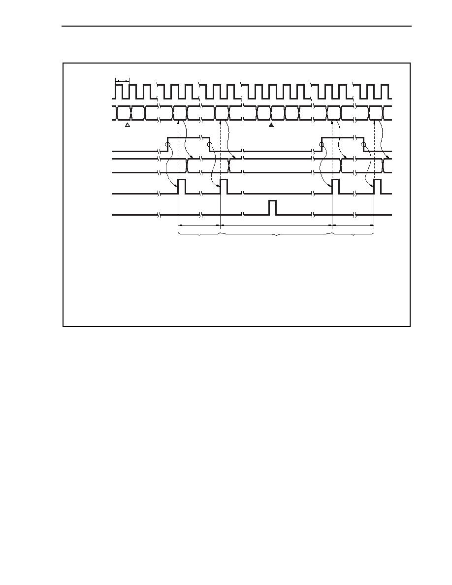
Figure 7-16. Cycle Measurement Operation Timing Example
0001H
0000H
0001H
0000H
FFFFH
D0
D1
D2
D3
D2
D1
D0
(D1
D0) × t
(D3
D2) × t
{(10000H
D1) + D2} × tNote
t
Count
clock
TMn
register
INTPn0
(input)
CCn0
register
INTCCn0
interrupt
INTOVFn
interrupt
No overflow
Overflow occurs
No overflow
Clear
Count start
Note
When an overflow occurs once.
Remarks 1. D0 to D3: TMn register count values
t: Count clock cycle
2. In this example, the valid edge of the INTPn0 input has been set to both edges (rising and falling).
3. n = 0, 1
发布紧急采购,3分钟左右您将得到回复。
相关PDF资料
PIC16F689-I/SO
IC PIC MCU FLASH 4KX14 20SOIC
PIC16F689-I/ML
IC PIC MCU FLASH 4KX14 20QFN
PIC16F685-I/SO
IC PIC MCU FLASH 4KX14 20SOIC
PIC16F886-I/SO
IC PIC MCU FLASH 8KX14 28SOIC
PIC18LF6680T-I/L
IC PIC MCU FLASH 32KX16 68PLCC
PIC16C54C-20I/SS
IC MCU OTP 512X12 20SSOP
PIC16C621A-20/P
IC MCU OTP 1KX14 COMP 18DIP
PIC18F4439-E/P
IC PIC MCU FLASH 6KX16 40DIP
相关代理商/技术参数
PIC24F08KL401T-I/MQ
功能描述:16位微控制器 - MCU 8KB FLASH 1KB RAM 512B 3V 10-BIT ADC RoHS:否 制造商:Texas Instruments 核心:RISC 处理器系列:MSP430FR572x 数据总线宽度:16 bit 最大时钟频率:24 MHz 程序存储器大小:8 KB 数据 RAM 大小:1 KB 片上 ADC:Yes 工作电源电压:2 V to 3.6 V 工作温度范围:- 40 C to + 85 C 封装 / 箱体:VQFN-40 安装风格:SMD/SMT
PIC24F08KL401T-I/SO
功能描述:16位微控制器 - MCU 8KB FLASH 1KB RAM 512B 3V 10-BIT ADC RoHS:否 制造商:Texas Instruments 核心:RISC 处理器系列:MSP430FR572x 数据总线宽度:16 bit 最大时钟频率:24 MHz 程序存储器大小:8 KB 数据 RAM 大小:1 KB 片上 ADC:Yes 工作电源电压:2 V to 3.6 V 工作温度范围:- 40 C to + 85 C 封装 / 箱体:VQFN-40 安装风格:SMD/SMT
PIC24F08KL401T-I/SS
功能描述:16位微控制器 - MCU 8KB FLASH 1KB RAM 512B 3V 10-BIT ADC RoHS:否 制造商:Texas Instruments 核心:RISC 处理器系列:MSP430FR572x 数据总线宽度:16 bit 最大时钟频率:24 MHz 程序存储器大小:8 KB 数据 RAM 大小:1 KB 片上 ADC:Yes 工作电源电压:2 V to 3.6 V 工作温度范围:- 40 C to + 85 C 封装 / 箱体:VQFN-40 安装风格:SMD/SMT
PIC24F08KL402
制造商:MICROCHIP 制造商全称:Microchip Technology 功能描述:Low-Power, Low-Cost, General Purpose 16-Bit Flash Microcontrollers with nanoWatt XLP Technology
PIC24F08KL402-I/ML
功能描述:16位微控制器 - MCU 8KB FLASH 1KB RAM 512B 3V 10-BIT ADC RoHS:否 制造商:Texas Instruments 核心:RISC 处理器系列:MSP430FR572x 数据总线宽度:16 bit 最大时钟频率:24 MHz 程序存储器大小:8 KB 数据 RAM 大小:1 KB 片上 ADC:Yes 工作电源电压:2 V to 3.6 V 工作温度范围:- 40 C to + 85 C 封装 / 箱体:VQFN-40 安装风格:SMD/SMT
PIC24F08KL402-I/MQ
功能描述:16位微控制器 - MCU 8KB FL 1KB RAM 512B 3V 10-bit ADC RoHS:否 制造商:Texas Instruments 核心:RISC 处理器系列:MSP430FR572x 数据总线宽度:16 bit 最大时钟频率:24 MHz 程序存储器大小:8 KB 数据 RAM 大小:1 KB 片上 ADC:Yes 工作电源电压:2 V to 3.6 V 工作温度范围:- 40 C to + 85 C 封装 / 箱体:VQFN-40 安装风格:SMD/SMT
PIC24F08KL402-I/SO
功能描述:16位微控制器 - MCU 8KB FLASH 1KB RAM 512B 3V 10-BIT ADC RoHS:否 制造商:Texas Instruments 核心:RISC 处理器系列:MSP430FR572x 数据总线宽度:16 bit 最大时钟频率:24 MHz 程序存储器大小:8 KB 数据 RAM 大小:1 KB 片上 ADC:Yes 工作电源电压:2 V to 3.6 V 工作温度范围:- 40 C to + 85 C 封装 / 箱体:VQFN-40 安装风格:SMD/SMT
PIC24F08KL402-I/SP
功能描述:16位微控制器 - MCU 8KB FLASH 1KB RAM 512B 3V 10-BIT ADC RoHS:否 制造商:Texas Instruments 核心:RISC 处理器系列:MSP430FR572x 数据总线宽度:16 bit 最大时钟频率:24 MHz 程序存储器大小:8 KB 数据 RAM 大小:1 KB 片上 ADC:Yes 工作电源电压:2 V to 3.6 V 工作温度范围:- 40 C to + 85 C 封装 / 箱体:VQFN-40 安装风格:SMD/SMT